
What's an acceptable leak rate for your part? The honest answer is: it depends. A leak rate that passes under controlled lab conditions can mean something entirely different once that same part is exposed to heat, cold, moisture, or pressure changes in the field.
Getting the leak rate calculation right and getting the test to run efficiently comes down to two things:
-
Understanding the calculations behind the number
-
Controlling the real-world variables that can slow down your test cycle
This post breaks down how to derive an accurate leak rate target using the ideal gas law, and shares the practical, floor-level factors that determine how fast, and how reliably, your leak test actually runs.
Need Help Determining Your Leak Rate? Click Here
Why "Acceptable" Leak Rate Depends on Context
Leak rates are standardized in scc/m (standard cubic centimeters per minute), benchmarked against atmospheric pressure at sea level. North American convention uses 20°C as the reference temperature; European convention typically uses 0°C, referred to as "normalized" flow.
That standard number only tells part of the story. If a component will actually operate somewhere hotter, colder, wetter, or at a different pressure than the benchmark condition, a leak rate that looked acceptable in the test lab may not hold up once the part is in service. Defining the right target leak rate means starting with how, and where, the part will actually be used—not just what passes on the test bench.
How Leak Rate Is Actually Calculated: The Ideal Gas Law
Every leak test—no matter the method—is governed by the same physics: the ideal gas law, which relates pressure, volume, and temperature in a closed system (PV = nRT). If temperature changes during a test, pressure inside the part changes too, which is why controlling and accounting for temperature matters just as much as controlling for a true leak.
Click on the image to see a larger version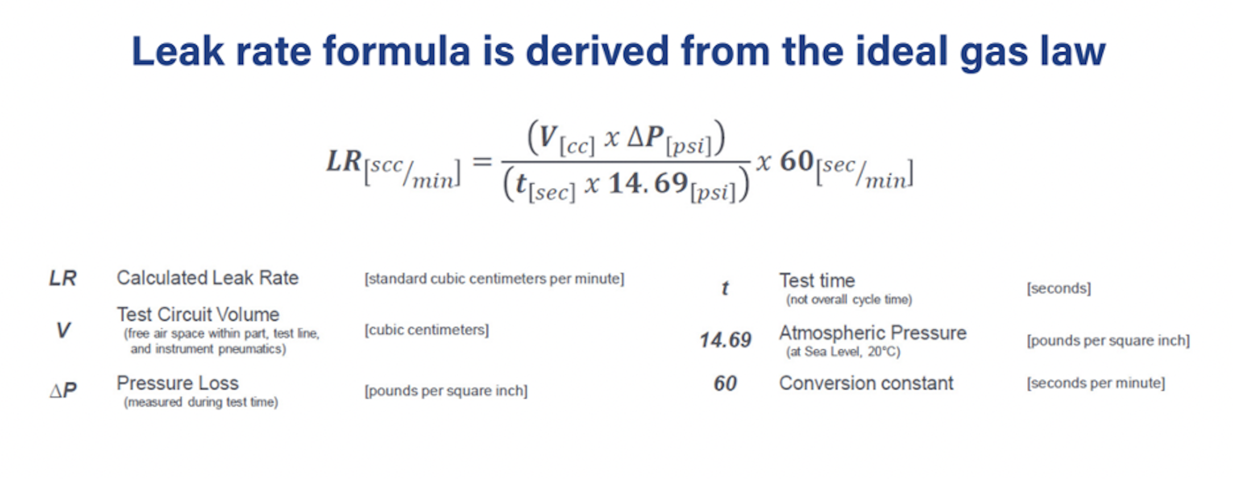
Working from the ideal gas law, you can derive a leak rate formula based on the moles of gas lost from the test volume over a given time period. In practice, the test volume, temperature, and atmospheric pressure are treated as known constants, and the leak rate is calculated as the volume of gas (measured under standard atmospheric conditions) that escapes from the part over a specified test time.
See the Application Note for Full Leak Rate Formula →
Understand the "Tare" Factor
Here's a detail that trips up a lot of test programs: most tests don't run long enough to let every dynamic effect, including thermal changes, volume shift, virtual leaks created by the test process itself fully settle out. That means even a non-leaking "master" part will show a small, consistent pressure loss during a test cycle.
To account for this, leak rate calculations include a tare factor (sometimes called the "No Leak Loss" value). It's the pressure loss measured on a known-good, non-leaking master part over the test time, and it's established during calibration alongside the part and system test volume. Subtracting this baseline from your measured pressure loss (and dividing by test time and atmospheric pressure, then converting to your unit of choice) gives you an accurate, corrected leak rate.
Getting the tare factor right is what separates a leak rate value you can trust from one that could be hiding problems.
Choosing the Right Leak Test Technology for the Job
The ideal leak rate—and the ideal way to measure it—has to be determined case-by-case, based on part geometry, leak path, usage context, and the cost of a failure in the field. A few starting points:
- Pressure decay: Best for open parts that will be sealed and pressurized internally.
- Differential pressure decay: Ideal for ingress protection testing (IP67 and similar standards), high test pressures, or very small leak rates that need a shortened cycle time.
- Volumetric fill pressure decay: Suited to sealed parts that can't be pressurized internally.
- Tracer gas (sniff, accumulation, or hard vacuum mass spec): Often the best option for large parts with low leak rates, parts that expand under pressure, or applications where temperature and pressure swings threaten repeatability.
Choosing a technology that can resolve the measurement you need without being thrown off by external variables is the first step toward a reliable test.
8 Ways to Control External Variables and Speed Up Cycle Time
A leak test can be accurate in theory and still run too slow—or produce misleading results—if the physical test setup isn't optimized. The most common source of false readings isn't the part; It’s leaking seals, fittings, valves, or other factors that can affect pressure loss measurements. Below are some factors to consider in your test set up to ensure a reliable, repeatable reading:
- Sealing: Use leak test connectors and seals with a mechanical component that physically locks to the part and ensures correct orientation, with feedback confirming proper seating pressure before the cycle starts.
- Pressure control: Fluctuating supply-line pressure affects both fill time and seal performance. A regulated accumulation tank at the test station smooths this out.
- Seal durometer: Softer seals form faster and easier but wear out sooner; harder seals last longer but demand more operator diligence. The best choice depends on your production environment, contact surface, target test pressure, and cycles per shift.
- Plumbing: Keep the part as close to the test instrument as possible. A shorter hose means less air volume in the circuit—less air to fill and less air that needs to reach thermal equilibrium. Hose diameter and material matter too.
- Fixturing: Make sure the part is held securely enough that it can't shift and compromise the seal mid-cycle.
- Internal geometry: For parts with multiple internal chambers separated by restrictions or narrow passages, connect to both sides of each chamber so you're not filling through a bottleneck.
- Fast-fill through large valves: Larger valves (½" or more) reduce system restriction, increase flow rate, and let the part fill (and exhaust) faster at the end of the cycle.
- Digital technology: Modern, low-noise electronics for pressure and flow measurement reach a stable, accurate reading faster, directly shortening the cycle time needed for a reliable pass/fail.
Address these one at a time and the gains compound; faster fill, more stable readings, and a shorter path to a confident pass/fail decision.
Questions About Leak Testing? Talk to the Experts at CTS
Leak testing involves a lot of interacting variables; leak rate targets, part geometry, seal design, plumbing, and test technology all affect each other. Getting the calculations and the setup right is what separates an optimized, repeatable test from a slow, uncertain one.
Contact the experts at Cincinnati Test Systems to discuss your leak test application and make sure you have the right test approach for your requirements.




 Last Post