We often emphasize that everything leaks, even at a miniscule level. Thus, when determining a target leak rate, the question should not be if the test part will leak. Instead, it should be determining an acceptable degree of leakage for the part, given its function and typical operating conditions, and the level of risk associated with the leak.
When leak testing is done in data center cooling systems, the materials are often quite sensitive and vulnerable to leaks, and the level of risk with a leak can be quite high. In these applications, leaks could pose severe safety concerns and costly hardware failures affecting people’s daily lives across the globe. This is why the industry has such stringent requirements and evolving requirements as new technologies and cooling applications are introduced.

Factors that drive leak rates in data center cooling systems
The data center cooling industry continues to evolve, and thus the determination of ideal leak rates continues to evolve as well. As new cooling applications are being introduced, designs begin to dictate leak rate specifications. The main factors that will impact the leak rates are: leak path, part design and materials, and risk (or ramifications) of a leak.
Leak / Flow Path
The rate of flow, or leakage, is highly dependent on the physical characteristics of the leak path. This applies with typical leak paths, including:
- Thin wall flow path: This is a leak in a thin-walled material or o-ring seals.
- Laminar flow path: This is a very idealistic leak path found in manufactured leak standards, but not something normally designed into real products in the industry.
- Tortuous path: This is a longer leak path that may pass through multiple seals and barriers. Tortuous flow paths are most common in cooling technology applications.
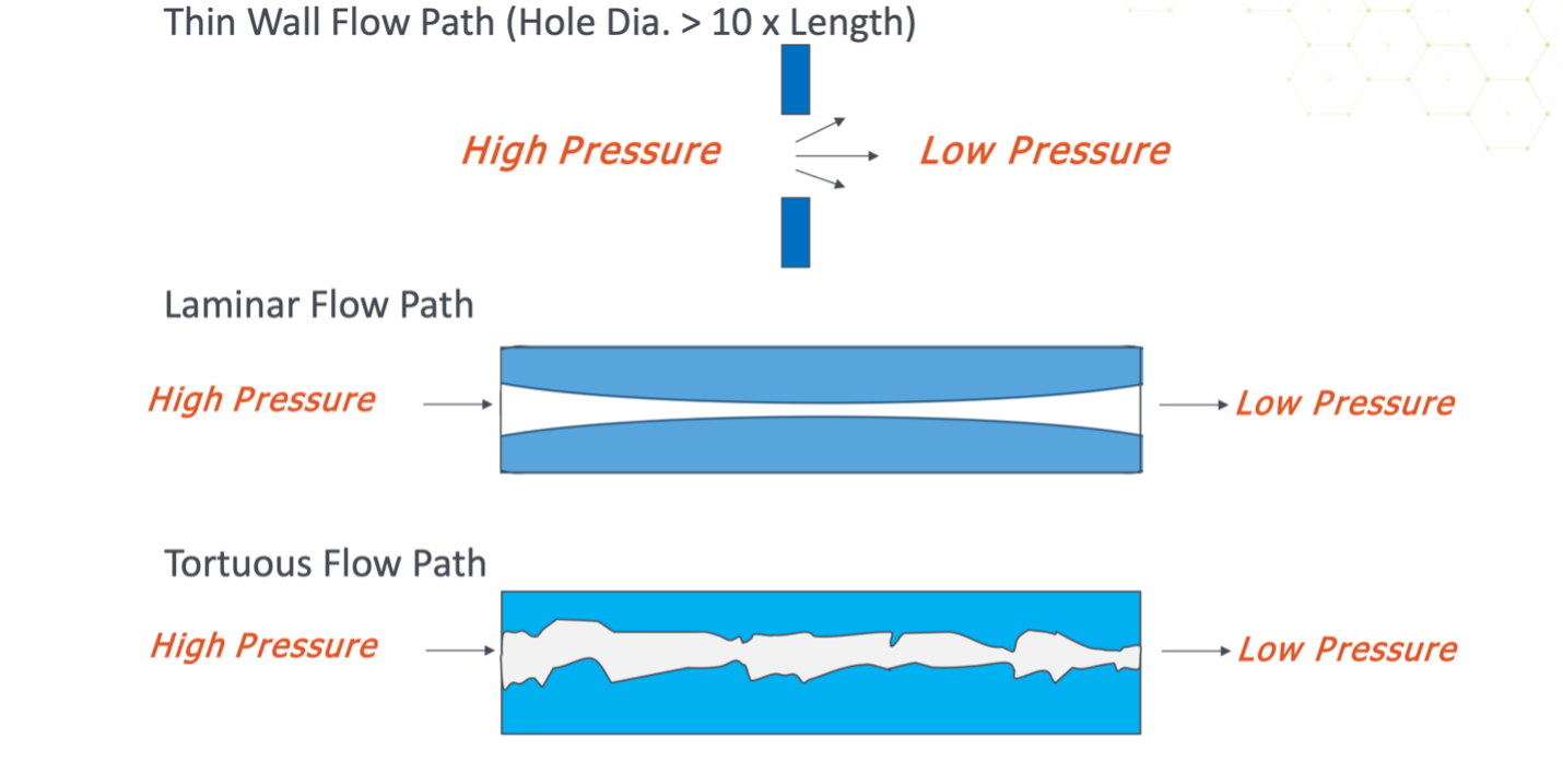
The same size hole will yield different leak rates depending on the length and the twists and turns of the leak path. The longer and/or more misshapen the path, the slower the rate. This impacts how you design your test, methods used, and how you use different sealing components.
Part Design
Part design, volume, and desired production rates have an impact on leak rates and test design. Small sub-assemblies have smaller volumes and leak rates that can often accommodate the use of lower-cost testing technologies like pressure decay and mass flow, etc.
However, larger parts or final assemblies have larger volumes, which can add complications to the leak testing process. Characteristics of a larger volume part will often lead to longer cycle times and impact leak rates. Different leak test methods and designs may need to be considered to balance the requirements of cycle time and leak rate for large volume parts. In these larger assemblies, leak rate is also impacted by the sub-assembly leak stack-up, meaning you may not be able to test lower than the stack-up of what the sub-assemblies allow.
Rise of Leak
The data center cooling industry. This is due to the vulnerability of the materials used (electronics and circuitry), as well as potential safety concerns (hazardous materials) and widespread effects of equipment failure.
For example: An automotive radiator has a typical leak rate of 4 sccm, 16-20 psi (50% water/50% glycol mix). A slight leak in a radiator will eventually heal itself over time due to oxidation. But an electronic system like those present in data centers can’t afford any level of oxidation, so the leak in the electronic system poses a greater risk, requiring a smaller leak rate.
It is also worth noting that gaseous leaks are becoming a higher concern as new products are being designed to operate using more environmentally-friendly methods, which can result in the use of more flammable gases. This elevates safety risks and concerns, and thus impacts the ideal leak rates.
Industry-standard leak rates based on cooling techniques
While it is illustrated above that leak rates can vary greatly based on part design factors and risks associated with the leaks, the below standards can act as a guideline for general applications.
|
Liquid cooling systems |
Standards |
|
Thick-walled parts, large seal surfaces, and massive weld/adhesive joints |
Leak rate could be >10 scc/m |
|
Typical non-water leak characteristics |
Leak rate ranges 0.5 – 10 scc/m |
|
Fine weld joints (laser welds) or small o-ring seals with exposure to electronic circuitry |
Leak rate could be 0.1 – 3 scc/m or less dependent upon risk of leak and damage to systems |
|
Refrigerant cooling systems |
|
|
A2L and A3 refrigerants, driven by fire codes |
Typical leak rate ranges from 1x10⁻⁵ scc/sec to ~5 x10⁻⁶ scc/sec |
Want to Learn More About Data Center Cooling Leak Testing?

CTS offers accurate and flexible options for evolving industry requirements
Given the rapid growth of the data center industry, the approaches and requirements of cooling technology continue to evolve, calling for smaller leak rates. For example, industry refrigerant changeover from HFC’s to HFO’s changes the permissible leak rates, and a manufacturers’ liquid leak rate could be originally specified for no liquid leak over 1 year and increase to no liquid leak over 5 years (from 1x10⁻³ to 1x10⁻⁵ scc/sec), due to the changing demands in the market.
This is why it is essential to set yourself up with a flexible leak test system that can evolve with your needs. CTS offers a wide range of leak test solutions to suit your needs, and a team of experts that can help you identify potential factors that could impact test accuracy and consistency of your test, and provide solutions to enhance efficiency and performance. Get in touch with us today to consult with a leak testing specialist!