

.png)
To prepare for calibration, the instrument must be set up for the correct test pressure and a repeatable leak testing sequence that includes fill, stabilize, isolation, test, exhaust and relax timers. This process is conducted manually by verifying filling the part to stable pressure, identifying the time for becoming stable, setting the isolation timer to 50% and achieving a 2:1 difference between known leaking parts and a non-leaking part.
Once complete, the operator will utilize a master part placed into the test fixture and press the instrument auto-calibrate button:
Using these setpoints, the leak test system establishes the “target flow window” for differential pressure decay leak detection.
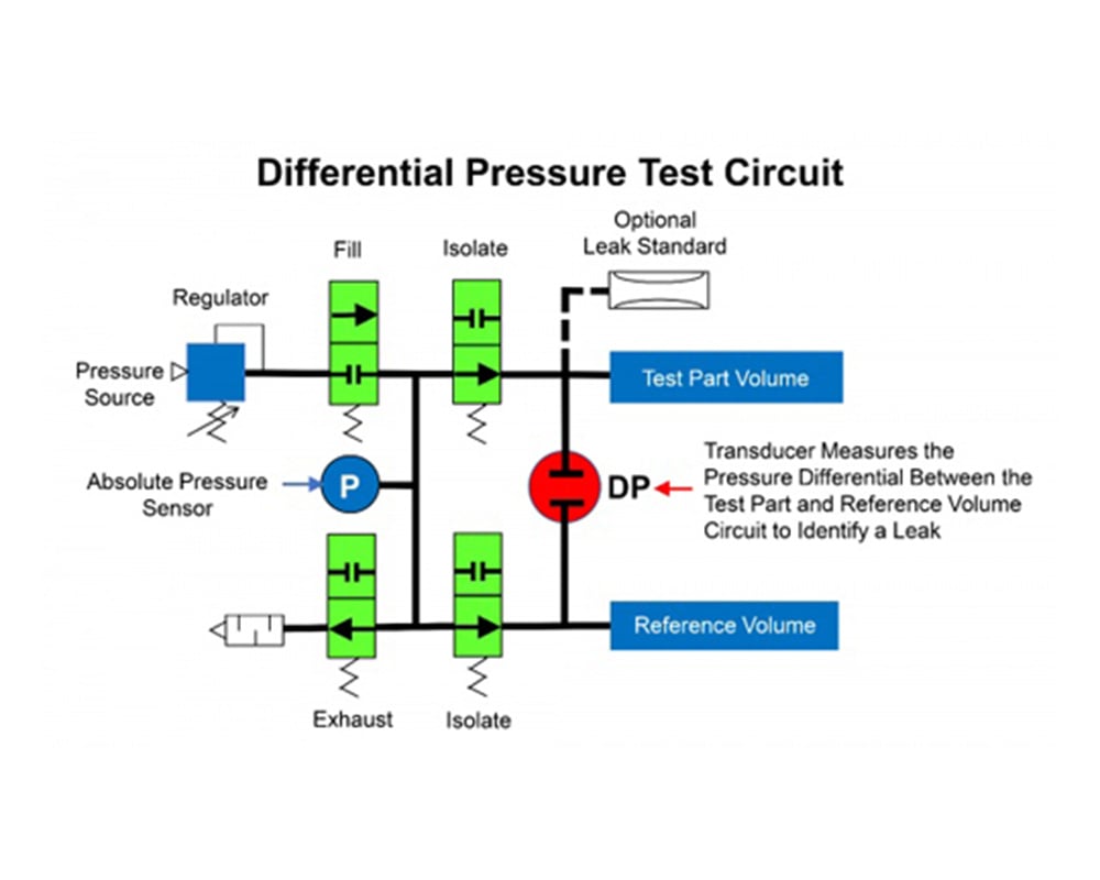
The test cycle fills a test part and a reference volume to a specified test pressure, the air source is cut off by the fill valve, test pressure stabilizes, and a reference air isolation valve is closed as the exhaust valve is open, isolating pressure on both sides of the differential pressure transducer. The transducer measures the pressure on both sides of the transducer throughout the test period. At the conclusion of the test, the instrument calculates the volumetric flow rate in scc/m based on the pressure loss measurement and test time . If the flow rate is within the “high and low limits window, the part passes the leak test. If outside the target limits, the part fails the leak test and is rejected. See diagram.
There are important factors to be considered to conduct and validate a reliable calibration:
Have questions about these factors?
Cincinnati Test Systems provides high precision differential pressure decay leak test systems: Sentinel MH, LPC 528, Sentinel C28, Blackbelt, Blackbelt Pro, and Sentinel I28. We are happy to help you determine which instrument best meets your differential pressure decay leak testing needs.