Successful Leak Testing for Inverters and Drive Units
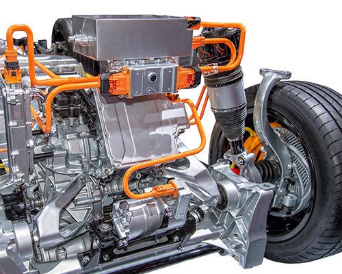
There are many new products being developed for the e-Mobility industry, testing requirements for these new products is crossing over from the established automotive industry. One of those examples is leak testing processes related to die castings. Products like Inverters, Drive Units, and even smaller Battery designs are housed in die cast components.
The unique characteristics of die cast components is the repeatable nature of these products related to their size plus the dimensional location of seal surfaces, inlet/outlet ports, and mounting surfaces. These qualities suit a diecast housing for automated and semi-automated leak testing loaded in and out of a test station.

The Importance of a Repeatable Calibration Routine
When these components are tested for leak rates and test pressures that are in the range of non-water ingress, technologies like pressure decay and differential pressure decay leak testing can be employed in the testing process. The key to repeatable leak testing of die castings with pressure decay and DP technology is the successful implementation of a repeatable calibration routine. The failures typically seen while testing die cast components is usually related to not accounting for inherent porosity of the components.
A successful calibration routine allows a long enough fill cycle to bring the part up to test pressure and maintain test pressure in the part after the stabilization cycle begins. when pressure falls drastically during the stabilization cycle it is usually related to access porosity still absorbing air pressure (allow additional time during the fill cycle to compress gas into the porosity rather than it being absorbed during the stabilize cycle shortens the overall cycle time).
Relax Period in a Two-Point Calibration Cycle
Additionally, during a two-point calibration cycle there should be a reasonable “Relax” period set between the first Non-Leak test and the second Known Leak Rate test. A reasonable relax period allows the originally pressurized master non-leak part to exhaust test pressure to atmosphere. This time not only allows measured pressure at the instrument to reach 0 psig, but also the compressed gas in the part porosity to exhaust to atmosphere. The reason this is important is because the same part will be pressurized again during the second Known Leak Rate test and if the porosity pressure is not completely released, the second test pressure drop will not be equivalent to the leak integrated into the second test. Thus, supplying erroneous leak rate measurements or by failing the calibration routine.
To achieve a passed calibration routine, adding relax time up to 180 seconds or more might be necessary for large castings (lots of surface area which means lots of porosity). In special cases you may need to utilize two different master parts. One master part as the Non-leak and another master part as the Known Leak.
Talk to an Expert
If you struggle with die cast part leak testing, CTS has over 40 years of experience supporting leak test solutions for die cast components. Our team can help new manufacturers establish repeatable and effective leak testing methods for these new products based on proven techniques and thoroughly vetted technologies.
Case Study: Leak Testing Electric Drive Housings for Porosity and Cracks
Porosity in castings adds a level of difficulty when conducting pressure decay leak testing. Special techniques can be utilized when designing a test station for these types of components. The Sentinel I28 instrument has specific functionality that allows users to implement this instrument into an effective leak testing process.

Application: Leak Testing Electric Drive Housings
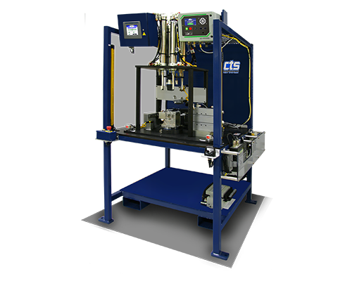
A supplier of electric drive housings needed to leak test their die cast parts for porosity and cracks to prevent water from leaking into the unit. Cincinnati Test Systems supplied a single station test system using pressure decay technology for leak testing the die cast drive housing. Air pressure measurement technology works well for die cast parts because air will flow through certain hole sizes that water will clog. This test system utilizes the Sentinel I28 pressure decay instrument.
Reducing Test Cycle Time to Meet Production Throughput
A single station test system was all that was needed to keep up with production throughput requirements for this assembly line. To reduce the test cycle time the part was loaded over a filler block built into the part nest and additional filler blocks were designed into the seal tooling. The filler blocks take up space inside the part reducing the over-all volume of the pressurized air inside the part.
By removing extra volume, the test cycle time is shortened because:
- There is less volume to pressurize during the fill cycle;
- The stabilization cycle is reduced for the same reason; and,
- Less time is necessary to measure a pressure drop in a small volume, especially when using DP technology.
Sentinel I28 Performs Controls Tooling
The Sentinel I28 leak test instrument has tooling control functionality built into its controls, the instrument supplies up to 5 independent tooling motion outputs and can receive feedback that those motions have advanced to a stop to continue the sequence. The instrument can be integrated with a PLC for easy integration using an ethernet connection of PROFINET, EtherNet/IP, or Telnet communication. Additionally, the instrument comes with direct contact I/O or serial communication if other methods of data transfer or control is expected.
The supplied machine had an Allen-Bradley PLC controlling its functions with EtherNet/IP communications. With every machine CTS supplies pre-programmed Add On Instructions at no additional cost. A PLC was integrated with this machine as there was additional functionality required for the testing process. One of those functions included laser sensors mounted in a position to measure that two independent ports were correctly threaded prior to sealing them for the leak test. Also, since this system tested two different types of parts, a scanned bar code was utilized to call up the correct leak test program and testing sequence for the specific part placed into the part nest.
Upon test completion accepted parts received a part mark while the test data and serial part number are combined by the instrument and supplied out to the PLC for data storage and display on the machine HMI. Failed parts are held in place by the test station clamps until the operator resets the machine for part removal. This operation helps remind operators to handle rejected parts differently from typically accepted parts that are automatically unclamped while the light curtains protect the operator by stopping any tooling motion if they put their hands into the machine while tooling is being activated.
Learn More about the Factors that Affect Cycle Time
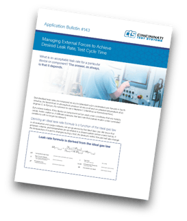
View the Managing External Forces to Achieve Desired Leak Rate, Test Cycle Time application bulletin for an overview of the variables that can impact leak test cycle time.

Talk to Us about Your Application
Contact CTS if you have similar requirements for conducting testing on die cast parts. Our team will work with you on the final requirements of your production testing needs to quote, design, and build an economically efficient test system for your application.
How to Establish an Acceptable Leak Rate
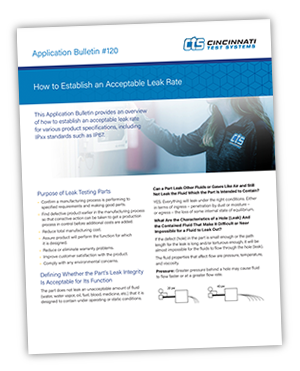
Learn more about non-water leak rates and establishing an acceptable leak rate for various product specifications.

