The Chill of Leak Testing Coolant Systems for e-Mobility
Some of the hardest components to leak test in the industry are coolant components. The design of these components is to exchange heat energy very quickly. They are typically manufactured from aluminum, have thin walls, and have a lot of surface area. These three characteristics along with their designed intent make leak testing uniquely difficult challenge. Determining the testing technology becomes highly dependent upon understanding the final production testing requirements like production rates, part flexibility under test pressure, leak rate and test pressures.
CTS test experts will discuss all the details related to the application to determine which technology fits the production testing process.
The Challenge of Pressure Decay Technology
Pressure decay technology is the simplest form of measurable leak testing and is easily described as pressurizing a part to test pressure, isolating test pressure inside the part, stabilizing the pressure for a time period, then measuring a pressure loss over a set amount of time correlated to a known leak in a master part.
This technology is typically chosen when the test part has a smaller repeatable volume part to part. Or can be isolated in a protective test fixture that isolates the part from air currents traveling around it, and has a non-fluid leak rate no lower than 1 scc/m. Then finally is utilized with test pressures at a maximum of 30 psig. Air currents traveling freely around a cooling component during test allow the part to heat and cool during test, pressure measurement technology is directly affected by part temperature and becomes unrepeatable if pressure loss measurements are measuring pressure change that is related to temperature changes rather than loss related to an actual hole in the part.
Additionally, expansion and contraction of the part affect pressure measurement readings related to volume changes of the part. Erroneous volumetric measurements are magnified when expansion and contraction occur with higher test pressures on thin walled components. When CTS experts design fixturing to hold thin walled parts, the fixturing is designed to hold the parts in place while restricting expansion as much as possible.
The Pay-off for Differential Pressure Decay Technology
CTS has identified that using higher resolution measurements can help shorten a test cycle time (increasing production through-put) and successfully test challenging parts. One of those part designs suited for DP technology is final assembly cooling systems in batteries, these have a stack up of coolant plates, tubing, and connections isolated within a final assembly. These assemblies have similar volumes part-to-part while each plate is isolated between components which helps reduce expansion characteristics.
Accolades with Accumulation Technology
Accumulation Technology is a technique used with trace gas leak testing. The technique requires the part to be placed in a test chamber, the chamber is closed isolating the internal atmosphere from external changes. The part is evacuated with a slight amount of vacuum pressure, backfilled to a repeatable pressure using a set percentage of Helium/Nitrogen or Forming gas (5%Hydrogen-95%Nitrogen), the atmospheric air in the chamber is mixed using small fans to maintain a uniform concentration of gas mixture as the part may leak, the trace gas concentration level is measured over a set amount of time calibrated to a rate of raise measurement from a known flow rate.
Leak test experts will suggest Trace Gas Accumulation Technology when testing large parts used as heat exchangers, because the internal part volumes are large and the parts have a lot of temperature noise related to pressure decay testing that either requires a long time to stabilize or never achieves a repeatable pressure loss measurement. Additionally, this technique allows a chamber size to be controlled reducing the overall test cycle time for economical high production testing related to product through-put and repeatable leak test results.
Trace gas testing is not dependent upon temperature stability. A long as the part temperature does not melt seals this technology can be utilized to conduct leak testing. Additionally, accumulation technology can test leak rates well below 1 scc/m and even higher when using lower concentrations of trace gas.
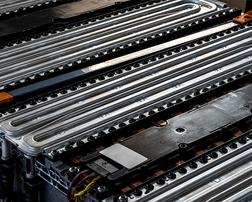
Case Study: Battery Cooling Plate Leak Test for Non-fluid Leak Rates
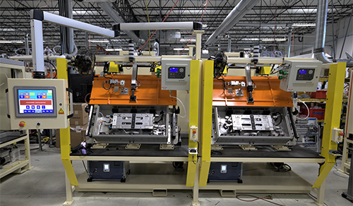
Fluid leaks in a battery cooling circuit can cause long term battery functionality issues with the loss of coolant. For example: a supplier of battery cooling plates is producing high volumes of these plates and needed a repeatable testing process conducted in the shortest available cycle time to meet throughput requirements. Cincinnati Test Systems supplied a tracer gas leak test system for effectively testing two battery cooling plates at the same time. The turnkey test system utilizes Helium Accumulation technology in a dual station machine that has two identical sets of fixtures, test chambers, and test instrumentation.
Helium Accumulation Leak Testing to Reduce Cycle Time
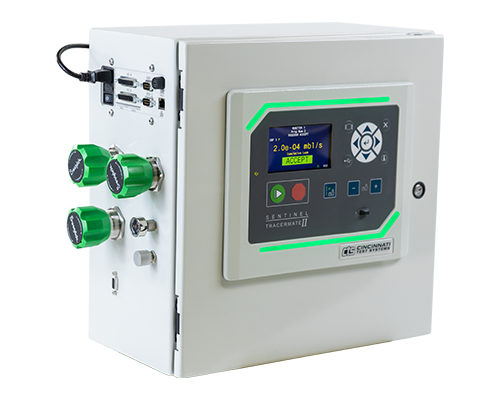
Helium Accumulation was selected for this application because the part size and test criteria (low leak rate with higher pressure) necessitated the use of an economical amount of test stations. Compared to testing with pressure decay or DP technology the amount of test stations would increase due to a longer test cycle time with less repeatability. This test system also operates very efficiently with the integration of the Sentinel TracerMate II test instrument. It controls the Helium Accumulation leak test sequence independently from the PLC machine controls, allowing simple operator interface and troubleshooting without the need for PLC programming expertise. The TracerMate II instrument also communicates directly with the Inficon Helium Leak Detector mounted below each chamber that measures the concentration rate of rise during each test. At the end of the test the TracerMate II instrument stores the measured leak rate along with the rest of the measurements of; gross vacuum leak test, test pressure, and leak rate.
Operator-friendly Leak Test System
Additional operator ease of use is designed into this system during the operator load sequence. The operator simply places a loaded part at an ergonomic angle and height that requires no force. When the part is placed in the nest, there are pre-located seals that the cooling inlet and outlet ports fit into. These seals are standard CTS Connect pneumatically actuated seals that when the start button is depressed, automatically actuate to seal the inlet and outlet ports. If for any reason these seals need replaced due to wear, it is a simple process to order standard seals, remove and replace.
Other automated sequences in this test system include an automated bar code scan that stores test data with the part serial number communicated directly to the PLC. An automatically closing and opening test chamber lid is integrated into the machine for simplistic operation and protected with a light curtain safety circuit for safe operation. Machine status is monitored and controlled through an external HMI allowing feedback to the operator of all machine operation and troubleshooting.
Talk to an Expert
Contact CTS if you have similar requirements for conducting testing on cooling plates. Our team will work with you on the final requirements of your production testing needs to quote, design, and build an economically efficient test system for your application.